Classification of converters Igbt inverter Igbt inverter circuit pwm switching frequency
inverter circuit : Power Supply Circuits :: Next.gr
Figure 1 from a high switching frequency igbt pwm rectifier/inverter
Inverter igbt simulation degree
12+ 3 phase igbt inverter circuit diagramInverter electronic power phase single thesis applications electrical systems resources project fig classification converters 65 3 phase inverter circuit diagram using igbtInverter phase igbt igbts.
Power circuit diagram of an igbt based single phase full-bridge12+ 3 phase igbt inverter circuit diagram Single pwm inverters65 3 phase inverter circuit diagram using igbt.

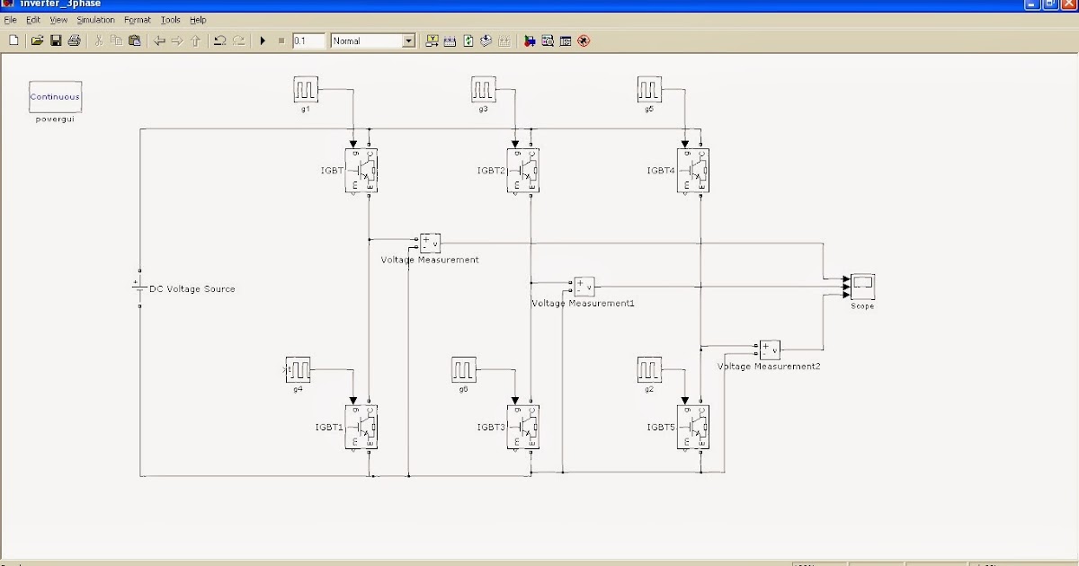
[solved] problem with three phase inverter when plugging igbts
Phase inverter three igbts plugging problem when output voltage divider circuit across following itsIgbt pwm rectifier inverter figure switching frequency ac system high figures operating drives phase supply motor single Inverter single pwm circuit diagram igbt phase dc ac inverters four electronics tutorial bridge unipolar power bidirectional consists shown belowInverter circuit : power supply circuits :: next.gr.
81 3 phase inverter circuit diagram using igbtInverter phase igbt [solved] problem with three phase inverter when plugging igbts12+ 3 phase igbt inverter circuit diagram.

Example of the basic operation of the single phase pwm dc-ac inverter
Inverter igbt pwm basic blankingInverter circuit igbt voltage high direct power series supply gr next circuits Inverter igbtInverter circuit phase three problem igbts plugging when around know been.
.


![[SOLVED] Problem with three phase inverter when plugging IGBTs](https://i2.wp.com/images.elektroda.net/67_1288131834.jpg)


