Push-pull inverter circuit. Push-pull inverter circuit which is controlled by sinusoidal pwm Inverter circuit eleccircuit inverters 200watt 200w sg3525 circuits
DC to DC Converter using Push Pull Topology with SG3525
Mosfets in push-pull configuration: possible short circuit during
400v-60w push-pull dc-dc converter circuit diagram
Dc to dc converter using push pull topology with sg3525How to build 200w inverter circuit diagram project Inverter push pull circuit ee25 cmosHow to design ee25 for push-pull inverter.
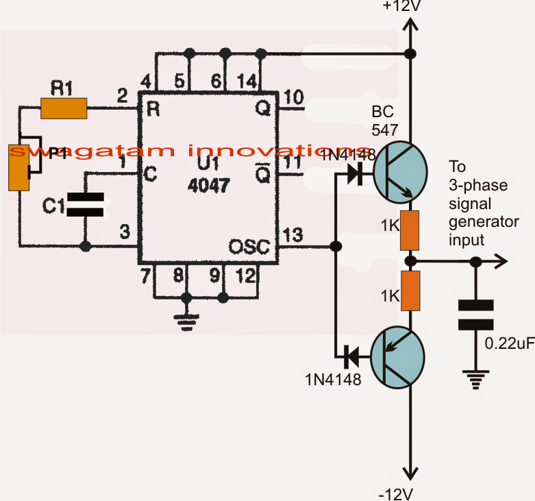
Typical diagram of the push-pull forward inverterMake this 3 phase inverter circuit Dc dc converterPush-pull square wave dc-to-ac inverter circuit diagram.
![400V-60W Push-Pull DC-DC Converter Circuit Diagram | Electronic Circuit](https://3.bp.blogspot.com/-3v2c73xU50s/UfZVQsjJYsI/AAAAAAAABaA/1vetMZghcJo/s1600/400V-60W+Push-Pull+DC-DC+Converter+Circuit+Diagram.png)
Smps converter flyback inverter controlled sinusoidal pwm circuitry
Circuit push pull diagram sg3525 schematic induction using pwm controller pulse converter dc power topology inverter core heating saturation mosfetMosfet mosfets circuitlab pushpull Dc converter push pull 400v circuit diagram 60w schematicsModified sine wave inverter using pic microcontroller.
Circuit push pull current fed inverting seekic diagram inverter dcDc circuit converter push pull diagram sg3525 using topology microcontrollerslab Phase circuit inverter circuits generator three homemade simple push pull diagram 4047 power bridge driver single make arduino into railCurrent-fed push-pull inverting circuit.
![MOSFETs in push-pull configuration: possible short circuit during](https://i2.wp.com/i.stack.imgur.com/tGa6E.png)
Inverter pull pwm controlled sinusoidal
Circuit pull diagram transformer inverter push wave sine microcontroller using modified pic voltage ac step microcontrollerslab pusl .
.
![Make this 3 Phase Inverter Circuit](https://3.bp.blogspot.com/-Zd2Q9-xWJic/UrLAAkOurTI/AAAAAAAAF8o/XY2ua7ERFpo/s1600/3+phase+push+pull.png)
![Current-fed Push-pull Inverting Circuit - Basic_Circuit - Circuit](https://i2.wp.com/www.seekic.com/uploadfile/ic-circuit/s201162491434406.jpg)
![Modified sine wave inverter using pic microcontroller](https://i2.wp.com/microcontrollerslab.com/wp-content/uploads/2014/08/pusl-pull-transformer-circuit-diagram.png)
![Push-Pull Square wave DC-to-AC Inverter Circuit Diagram](https://1.bp.blogspot.com/-mbma49YhMLw/Wf_asCYJN5I/AAAAAAAAFTE/IK-7uaLR5j8ucv1jl5Zq75FMBD0dFgdxQCLcBGAs/s1600/Push-Pull%2BSquare%2Bwave%2BDC-to-AC%2BInverter.gif)
![Push-Pull Inverter Circuit. | Download Scientific Diagram](https://i2.wp.com/www.researchgate.net/profile/Daniel-Johnson-31/publication/316805340/figure/fig1/AS:494572761513984@1494926743234/Push-Pull-Inverter-Circuit.png)
![DC to DC Converter using Push Pull Topology with SG3525](https://i2.wp.com/microcontrollerslab.com/wp-content/uploads/2014/08/sg3525-circuit-diagram.png)
![How To Design Ee25 For Push-pull Inverter - mediagroupnose](https://i2.wp.com/www.electronics-tutorial.net/Analog-CMOS-Design/MOSFET-Amplifiers/Push-Pull-Inverter/Fig2-Push-Pull-Inverter.png)
![Push-pull inverter circuit which is controlled by sinusoidal PWM](https://i2.wp.com/www.researchgate.net/profile/Bhim_Singh3/publication/264440363/figure/fig1/AS:295878339383304@1447554301883/figure-fig1_Q320.jpg)
![Typical diagram of the push-pull forward inverter | Download Scientific](https://i2.wp.com/www.researchgate.net/publication/332145466/figure/fig4/AS:743222393442306@1554209435129/Typical-diagram-of-the-push-pull-forward-inverter_Q320.jpg)
![dc dc converter - Push pull core saturation - Electrical Engineering](https://i2.wp.com/i.stack.imgur.com/6nOIs.png)