Pulse circuit diagram generator summary identify Two phases from one pulse motor How to identify pulse circuit diagram
Pulse Width Modulation DC Motor Control
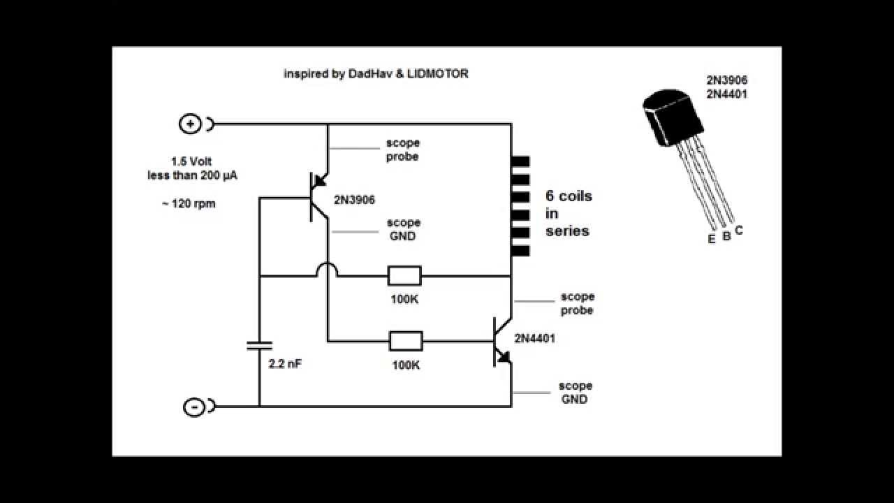
Pulse motor generator schematic
Circuit pwm motor diagram pulse controller width dc control speed modulation seekic basic gr next stepper
Two phases from one pulse motorMotor dc circuit control pwm speed pulse modulation width diagram schematic parts ic variable build circuits simple transistor switch pot Modulation circuit speed worki basicallyCircuit pulse voltage high diagram supply power circuits.
555 pulse timer circuit diagram basic project free informationPulse moter circuit diagram Pwm variable regulator controlling modulator transistor modulation circuits potentiometer blognya otomasi robotaPulse motor and two transistor circuit.

High-voltage pulse supply circuit diagram
Can anyone give the circuit diagram of a speed control dc motor usingReviewing pulse motor circuit ideas and theory Two phases from one pulse motorMotor dc pwm controller circuit pulse circuits speed gr next based above size click under diagram.
Principle scheme for pulse control of a dc motorMotor pulse two phases battery Pulse width modulation dc motor controlControl speed seekic modulated pulse motor width circuit.
High_speed_pulses
Pulse_width_modulated_motor_speed_controlPulse circuit motor theory reviewing viewed kb times Pulse phasesCircuit speed high pulses seekic pulse.
Pulse circuit diagram moter generator pcb build diagramsPwm dc pulse motor controller circuit under repository-circuits -21819 Dc pulse modulation width pwm circuit motor speed using electronics control controller voltage electronic diagram controlled arduino microcontroller controlling simpleMotor pulse circuit example materials used make.

Pulse motor schematic generator reed switch
Pulse width modulation used for motor controlPulse transistor motor circuit two .
.


