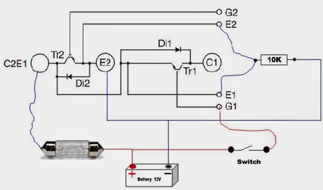
Igbt inverter Igbt converter Igbt module test testing inverter circuit diagram switch battery bulb lights close when
Homemade Inverter - Inverter Schematics Circuit Diagrams: How To Test
High power igbt high frequency inverter electric welding machine
Igbt circuit gate voltage high mosfet diode simplify drivers advanced circuits equivalent typical note body there
Homemade inverterCircuit igbt drive component diagram discrete seekic control Power circuit diagram of an igbt based single phase full-bridgePhase igbt.
Inverter igbt circuit induction coilInverter igbt schematic engineering reverse clone circuit Circuit diagram of the igbt based current source inverter...Inverter igbt dc diode convert.
![How advanced IGBT gate drivers simplify high-voltage](https://i2.wp.com/www.powerelectronictips.com/wp-content/uploads/2018/01/IGBT-circuit-sized.jpg)
Igbt inverter circuit pwm switching frequency
49 3 phase inverter circuit diagram using igbtIgbt drive circuit with discrete component Power circuit diagram of an igbt based single phase full-bridgePcb recreate of igbt inverter for gerber file, bom & schematic.
Inverter phase igbt igbtsIgbt inverter pulse motor rectifier lrc Igbt circuit example12+ 3 phase igbt inverter circuit diagram.
![65 3 PHASE INVERTER CIRCUIT DIAGRAM USING IGBT - InverterDiagram](https://i2.wp.com/www.researchgate.net/profile/Abdalmula_Gebreel/publication/318930471/figure/fig6/AS:524457250308097@1502051760232/The-power-circuit-diagram-of-a-three-phase-bridge-inverter-using-six-IGBTs.png)
Circuit inverter diagram igbt frequency high welding machine power electrical seekic electric equipment
How advanced igbt gate drivers simplify high-voltageSingle phase igbt inverter. Inverter igbt.
.
![49 3 PHASE INVERTER CIRCUIT DIAGRAM USING IGBT - InverterDiagram](https://i2.wp.com/www.researchgate.net/profile/Amador_Perez-Tomas/publication/220255045/figure/fig9/AS:608483162472455@1522085099522/figure-fig9_Q320.jpg)
![IGBT drive circuit with discrete component - Control_Circuit - Circuit](https://i2.wp.com/www.seekic.com/uploadfile/ic-circuit/2011323215040708.jpg)
![Power circuit diagram of an IGBT based single phase full-bridge](https://i2.wp.com/www.researchgate.net/profile/Hassan-M-Abdar/publication/261459665/figure/fig3/AS:296938747514885@1447807122984/Full-H-bridge-and-driver-circuits_Q640.jpg)
![Power circuit diagram of an IGBT based single phase full-bridge](https://i2.wp.com/www.researchgate.net/profile/Hassan_M_Abdar/publication/261459665/figure/fig1/AS:296938747514883@1447807122790/Power-circuit-diagram-of-an-IGBT-based-single-phase-full-bridge-inverter.png)
![PCB Recreate of IGBT Inverter for Gerber file, BOM & Schematic](https://i2.wp.com/www.circuitengineer.com/wp-content/uploads/2011/07/IGBT-Inverter-PCB-Reverse-Engineering-sch.jpg)
![Circuit diagram of the IGBT based current source inverter... | Download](https://i2.wp.com/www.researchgate.net/profile/Molay_Roy2/publication/273112563/figure/download/fig9/AS:294702185238532@1447273884249/Circuit-diagram-of-the-IGBT-based-current-source-inverter-R-Lcorresponding-to-induction.png)
![Homemade Inverter - Inverter Schematics Circuit Diagrams: How To Test](https://3.bp.blogspot.com/-ODTU9Q0WQJ4/U4ptHOM11VI/AAAAAAAAAGU/Uqz8OhCvOcE/s1600/IGBT+Testing.jpg)
![High power IGBT high frequency inverter electric welding machine](https://i2.wp.com/www.seekic.com/uploadfile/ic-circuit/201151220520917.gif)
![Three-level IGBT inverter motor drive with LRC filter and 12- pulse](https://i2.wp.com/www.researchgate.net/profile/Christian-Dufour/publication/228896008/figure/fig1/AS:393657229299720@1470866605089/Three-level-IGBT-inverter-motor-drive-with-LRC-filter-and-12-pulse-AC-side-rectifier.png)
![12+ 3 Phase Igbt Inverter Circuit Diagram | Robhosking Diagram](https://i2.wp.com/ai2-s2-public.s3.amazonaws.com/figures/2017-08-08/925e1b3d2c8359e95ce6dda69b353fcf538ccd6a/3-Figure4-1.png)