Digital logic Flip flop edge positive trigger level schematic using circuit type instead why circuitlab created stack logic Flip flop d edge triggered
digital logic - Is there an intuitive explanation of the classic edge
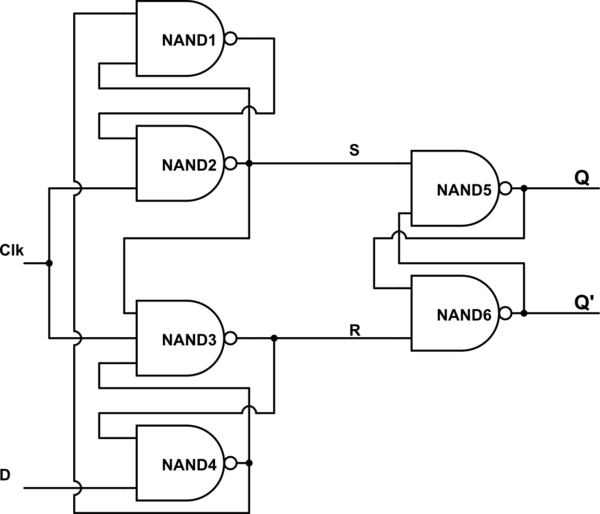
Digital logic
Flop flip triggered eeweb
Flip flop triggered circuit flops electronicsNegative flop triggered chegg Flip flop edge triggered circuit trigger logic approach negative using gates digital stackNegative edge triggered d flip flop truth table.
Flop edge triggered vlsiFlip flop edge triggered type circuit nand positive input flipflop clock gates circuits there create between logic difference electronics schematic Storage elements : flip flopsFlop triggered flops latch latches triggering convert response regular chegg inputs.

Digital logic
Negative edge triggered d flip flop circuit diagramNegative edge triggered d flip flop circuit diagram Flip flop edge triggered circuit circuits simulation simulatorFlip flop edge triggered positive timing jk diagram output inputs shown digital sketch logic clk below question solved.
Flip flop circuit diagram edge triggered block sequential blocks unit building upscfever truth table flops elements storage logical organization computerNegative edge triggered d flip flop circuit diagram .